http://free-electrons.com/blog/beagle-labs/
The above link has information about doing practical labs with beagle board. This link has valuable information for beagle board users.
This lecture slides are also useful in order to learn about building your own file system, boot loader for beagle board from scratch.
Monday, February 22, 2010
Thursday, February 18, 2010
Stand-Alone Demos
Stand-Alone Demos can boot on any beagle board without even setting the NAND. Any SD card demo can be made Stand-Alone using a custom boot.scr file. Using this boot.scr file will enable an user to boot a demo on any beagle board without even setting the environment variables or NAND. Custom boot.scr file can also work with empty NAND.
Custom boot.scr file
In order to make custom boot.scr file you need:
1) mkimage
$ sudo apt-get install uboot-mkimage
2) vim text editor
Procedure:
1) create an empty text file.
2) type the format for boot.scr file in the empty text file: NOTE: see below in Text File Format:
3) once the text file is made run this mkimage command: $ mkimage -A arm -O linux -T script -C none -a 0 -e 0 -n 'Execute uImage.bin' -dname of the text file boot.scr
NOTE: this will create an executable file named "boot.scr"
4) Insert the SD card and mount the fat partition
$ sudo mount /dev/sdb1 /media/card
NOTE: in some versions of linux, sdb1 might be sdc1.
In order to check type $ cat /proc/partitions and look at the second last line.
5) copy the boot.scr file in the fat partition of the SD card
6) Unmount the fat partition
$ sudo umount /dev/sdb1
7) insert the SD card in the beagle board
8) hold the user button while powering on the bb
NOTE: user button is the near the SD card slot. It is towards the end of the board.
9) enjoy your Stand-Alone Demo ! ! !
Text File Format:
NOTE: This is a Shell Script Format: http://en.wikipedia.org/wiki/Shell_scripting
if fatload mmc 0 0xboot address uImage
then
setenv bootargs 'environment variables'
echo ***** stand-alone demo *****
fi
bootm 0xboot address
NOTE: There has to be a space before setenv & echo
NOTE: The line "echo" above is optional. This line prints information on the screen. for example, the above line prints "***** stand-alone demo *****" on the screen.
NOTE: environment variables and boot address depends on a particular demo.
EXAMPLE: if bootcmd is "setenv bootcmd 'mmc init; fatload mmc 0 0x80300000 uImage; bootm 0x80300000'"
then the bootaddress will be 80300000.
Bootargs EXAMPLE: setenv bootargs 'console=ttyS2,115200n8 root=/dev/mmcblk0p2 rootwait omap.dssmode=dvi:1024x768-16@60'
Additional Resources:
http://groups.google.com/group/beagleboard/browse_thread/thread/e97fb9895c09a98c
Instructions regarding partitioning the SD card:
http://www.sakoman.com/OMAP3/preparing-a-bootable-sd-card.html
Demo images of Gnome can be found here:
http://www.sakoman.com/component/option,com_phocadownload/Itemid,60/view,sections/
Custom boot.scr file
In order to make custom boot.scr file you need:
1) mkimage
$ sudo apt-get install uboot-mkimage
2) vim text editor
Procedure:
1) create an empty text file.
2) type the format for boot.scr file in the empty text file: NOTE: see below in Text File Format:
3) once the text file is made run this mkimage command: $ mkimage -A arm -O linux -T script -C none -a 0 -e 0 -n 'Execute uImage.bin' -d
NOTE: this will create an executable file named "boot.scr"
4) Insert the SD card and mount the fat partition
$ sudo mount /dev/sdb1 /media/card
NOTE: in some versions of linux, sdb1 might be sdc1.
In order to check type $ cat /proc/partitions and look at the second last line.
5) copy the boot.scr file in the fat partition of the SD card
6) Unmount the fat partition
$ sudo umount /dev/sdb1
7) insert the SD card in the beagle board
8) hold the user button while powering on the bb
NOTE: user button is the near the SD card slot. It is towards the end of the board.
9) enjoy your Stand-Alone Demo ! ! !
Text File Format:
NOTE: This is a Shell Script Format: http://en.wikipedia.org/wiki/Shell_scripting
if fatload mmc 0 0xboot address uImage
then
setenv bootargs 'environment variables'
echo ***** stand-alone demo *****
fi
bootm 0xboot address
NOTE: There has to be a space before setenv & echo
NOTE: The line "echo" above is optional. This line prints information on the screen. for example, the above line prints "***** stand-alone demo *****" on the screen.
NOTE: environment variables and boot address depends on a particular demo.
EXAMPLE: if bootcmd is "setenv bootcmd 'mmc init; fatload mmc 0 0x80300000 uImage; bootm 0x80300000'"
then the bootaddress will be 80300000.
Bootargs EXAMPLE: setenv bootargs 'console=ttyS2,115200n8 root=/dev/mmcblk0p2 rootwait omap.dssmode=dvi:1024x768-16@60'
Additional Resources:
http://groups.google.com/group/beagleboard/browse_thread/thread/e97fb9895c09a98c
Instructions regarding partitioning the SD card:
http://www.sakoman.com/OMAP3/preparing-a-bootable-sd-card.html
Demo images of Gnome can be found here:
http://www.sakoman.com/component/option,com_phocadownload/Itemid,60/view,sections/
Tuesday, February 9, 2010
Other OMAP3530 Processors
Embest DevKit8000 Evaluation Board
http://armkits.com/Product/devkit8000.asp
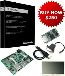
TechNexion - Thunder
http://www.technexion.com/index.php/thunderpack
TechNexion - Inferno Interface Board for TAO-3530 Series
http://www.technexion.com/index.php/inferno
TechNexion - TAO-3530 System Module
http://www.technexion.com/index.php/tao-3530
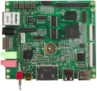
http://armkits.com/Product/devkit8000.asp

- Dimensions: 110mm x 95mm
- Working temperature: 0°C to 70°C
- Processor: TI OMAP3530 microprocessor with 600MHz ARM Cortex-A8 RISC Core
- Power supply: +5V
- 128MB DDR SDRAM, 166MHz
- 128MB NAND Flash, 16bit
- LCD/Touch Screen interface (50-pin FPC connector, support resolution up to 2048*2048, optional VGA8000 module can connect via LCD interface)
- DVI high-resolution image output port (HDMI interface, support 720p, 30fps signal)
- S-Video display interface
- One audio input interface (3.5mm audio jack)
- One 2-channel audio output interface (3.5mm audio jack)
- One 10/100M Ethernet interface (RJ45)
- One High-speed USB2.0 OTG port (Mini USB type interface)
- One High-speed USB2.0 Host port (USB A type interface)
- Two serial ports (one 3-wire RS232 serial port led out from 2.54mm 10-pin connector and one 5-wire TTL serial port led out from expansion connector)
- SD/MMC interface (supports 3.3V and 1.8V logic voltage)
- One camera interface (30-pin FPC connector, support CCD or CMOS camera, support analog camera module CAM8000-A for option)
- 6*6 keyboard interface
- One 14-pin Jtag interface
- Four buttons (Reset, Boot, User defined, On/Off)
- One expansion connector (2.0mm 40-pin SMT Female Pin Header, McSPI, McBSP, I2C, HDQ, GPIO are led out from this connector)
- Supports USB WiFi through WF8000-U module
- Supports GPS function through GPS8000-S module
- Supports GPRS function through GPRS8000-S module
- Support 3G function through CDMA8000-U module (CDMA2000 standard)
This particular board is user friendly since it has LCD touch screen interface. Also additional modules such as GPS, GPRS, 3G, USB WiFi make networking mobile on this board. This board also has Ethernet 10/100M interface, which does not require USB in order to access the internet.
TechNexion - Thunder
http://www.technexion.com/index.php/thunderpack

| |
| This board has wireless LAN, which is a very useful tool in order to acess the network without LAN cable. Also G-sensor on this board can prove very useful in gaming applications. | |
http://www.technexion.com/index.php/inferno
 1 mini-USB hosts
- 1 mini-USB device / OTG
- SD card slot
- Stereo audio in/out 3.5 mm
- 2W aplified speakers (L/R)
- S-video connector
- DVI-D signal by HDMI connector
- SPI, RS-232, UART, I2C, GPIO

TechNexion - TAO-3530 System Module
http://www.technexion.com/index.php/tao-3530
 128 MB Low power mobile DDR
- 256 MB NAND Flash
- Marvell 8686 802.11b/g
- Two 100 pin NAIS connectors
SPI, UART, USB HS, USB OTG,
I2C, PWM lines, 1-wire, MMC lines,
A/D lines, camera, audio in/out,
S-Video, LCD interface
 128 MB Low power mobile DDR
DRG (Digital Raster Graphics)
 http://topomaps.usgs.gov/drg/
The above image is of 7.5-minute Digital Raster Graphic.
DRGs are topographical images which are ultra high resolution, with a minimum of 250 dots per inch.
Using Beagle Board to process DRG's can be handy tool, because of its size and the fact that it consumes very little power. One way to process DRGs can be break them into tiles, and then joining them together again after processing. Beagle Board's DSP can be used to offload some work needed in order to process DRG's
Several beagle boards can be used with each beagle board processing one tile at a time.
IRC nicks ds2 and av500 were discussing about it
The thread can be found at: http://www.beagleboard.org/irclogs/index.php?date=2010-02-05#T23:28:16
Subscribe to:
Posts (Atom)